Discount Products: Look through products available for a 25% – 50% discount in 2020. The items provided on a first come, first serve basis. View Discounted Products
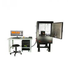
As atomic force microscopes continue to enter more and more areas of applications, especially in industry, production processes and quality control, standard AFM systems are often not suitable for the task at hand. For these cases, when you need the AFM to be fully integrated in a process, or your samples are too large for standard setups, Nanosurf offers the unique service of designing and developing custom AFM systems and stages that will allow you to perform your measurements with minimal disruption of your established process.
Key Features
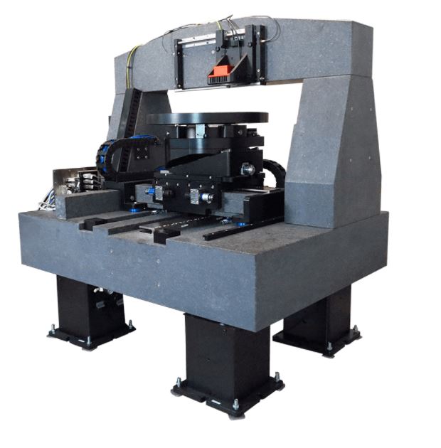
Curved surface
Automated XZΘ translation stage
Max. traverse path XZ/Θ
250/60 mm / 100°
Sample size
max. Ø380 mm x 220 mm
Stage size
450 mm x 550 mm x 460 mm
Noise level
<0.5Å
AFM measurements on large concave or convex samples require the scan head to rotate such that the cantilever approaches the surface under the same angle on every location. Economic full 360° manual rotation of the sample platform and motorized
XZΘ-travel ensures to reach every point on the sample.
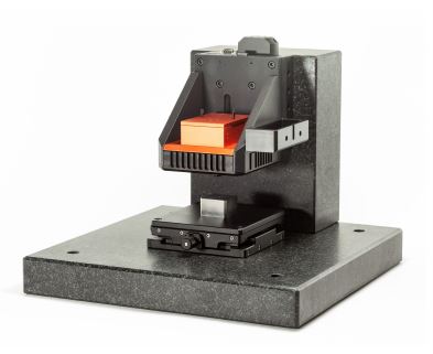
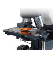
Handling
This micrometer transfer stage allows the examination of a sample with an inverted optical microscope, where the sample faces down, and with AFM, where the sample faces up. The sample – a glass lens – is fixed in place after the area of interest is located using the optical microscope and then flipped over and transferred to the AFM with a repositioning accuracy of better than 10µm.
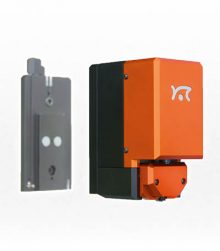
Levelling
Automated XYZΘΦ translation and goniometer stage
Max. traverse path XYZ/ΘΦ
72/46/5 mm / ±5°
Sample platform size
75 mm x 50 mm
Sample size
max. 75 mm x 50 mm x 13 mm
Precision alignment stage: two goniometer stages and three highly sensitive force sensors were incorporated to allow automated levelling of a sample plane with respect to the scan head within 0.005°. Humidity control and a custom built cantilever holder were developed to facilitate nano-imprint lithography. LEE, I.-Ning, et al. Large-area scanning probe nanolithography facilitated by automated alignment and its application to substrate fabrication for cell culture studies. JoVE (Journal of Visualized Experiments), 2018, Nr. 136, S. e56967. WANG, Shuai, et al. Large-area scanning probe nanolithography facilitated by automated alignment of probe arrays. RSC Advances, 2015, 5. Jg., Nr. 75, S. 61402-61409.
Key Benefits
Sometimes custom adaptations make the difference
Do you need to perform AFM measurements, but your samples are large, require special handling or your experiments go beyond established techniques and methods? We take your needs seriously and will jointly work with you on a solution. In close cooperation and in continuous dialog with you, our instrument development team will design and construct a system tailored to your exact needs. Contact us with a first description of your needs and we‘ll be happy to get back to you to discuss your project in depth.
Trust the Experts at Spectra Research Corporation
Spectra Research Corporation (SRC) offers a range of innovative high-quality scientific products and laboratory services to industrial and scientific markets throughout Canada.
Specifications
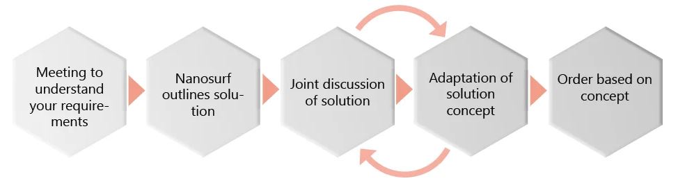
System workflow and specifications
Flex-ANA system workflow
Mounting and calibrating the cantilever
Automated measurement and calculation of deflection sensitivity and spring constant
Spring constant calibration based on the Sader Method
Resonance frequency and Q-factor extraction from thermal noise power spectrum
Frequency range 0–5 MHz
Sample loading and overview image
35 mm × 35 mm sample platform
Overview image covering up to 80 mm × 60 mm
Definition of measurement locations and conditions
Measurement locations can be defined on the optical overview image
Measurement conditions, e.g. contact force, indentation velocity or resolution, can be defined in the Flex-ANA software
Start of the automated measurement
Autonomous measurements at defined locations
Automatic sample approach at each location with a maximum approach range of 5 mm
Real-time data analysis (elastic modulus in the range of 0.1 kPa – 20 GPa(1), adhesion, height, slope of contact region)
Map and histogram are available for each analysis parameter
Analysis optimization
Integrated data browser with data preview
Various contact mechanics models (Hertz, Sneddon, DMT, 4-Sided Pyramid)
Results
Export of final histograms and maps
(1)Accessible modulus range depends on choice of cantilever