
 I’ve been hanging out with the Cypher Family of AFMssince the Cypher S was originally launched in 2008, so sometimes I take its vibration immunity for granted. Of course we can see isolated atomic point defects on a wooden desk — or on the show floor at the MRS meeting with several thousand attendees milling around! Doesn’t everyone?!?
Stepping back from that a bit, questions about resolution and noise rejection come up a lot in AFM. I thought it would be worth spending a little time i) talking about what makes Cypher special and ii) coming up with a demonstration of vibration immunity slightly more scientific than waiting for an earthquake with the Cypher sitting on a wooden table.
Design Considerations
AFMs are mechanical instruments. They are made of materials that distort their shape in response to external forces—specifically, sound and vibration. These distortions can cause noise, drift and damage of the tip and/or the sample surface. When we were in the early stage of designing the Cypher AFM, we wanted to make, among other things, a microscope that would be as immune to these external vibrations as possible. To do this, we built several prototypes to explore different ways of improving the resolution and stability of the instrument. In particular, we tried to identify the main weak point(s) to external vibrations.
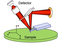 As shown in Figure 1 to the right, we divided the AFM into three separate components: (i) the optical detection system, (ii) the cantilever and (iii) the sample. The question we tried to answer was simple: Which of the three boundaries—between the detector and cantilever, the detector and sample or the cantilever and sample—was more susceptible to external vibration noise?
Figure 1. The three basic components of the AFM discussed here: the detector (typically an optical beam deflection sensor), the cantilever and the sample.
The cantilever detection system in most AFMs is an optical beam deflection system that consists of a mirror-like surface on the back of the cantilever, a laser that reflects from this surface, and a position-sensitive detector (PSD) that receives the reflected laser beam. When the cantilever bends, the light on the position-sensitive detector moves, and this motion is converted into a voltage that is used to infer the motion of the tip at the end of the cantilever. The cantilever acts as a carrier for a sharp tip that interacts with the sample surface. The sample is scanned in three dimensions relative to the detector and the cantilever.
Conventional AFM systems are arranged as shown in Figure 2a below with the cantilever and the optical detection system closely coupled, usually built into the same structure (typically called the “head”). At first blush, this is a very natural and sensible arrangement, where the head is a simple unit that turns cantilever deflection into a voltage signal used to operate the microscope and to measure tip-sample interactions. In our experiments and to our initial surprise, we discovered that the weak link in the AFM mechanics was at the boundary between the cantilever and the sample.
To minimize the effects of this weak link, we designed a system with two separate translation stages: one between the cantilever and sample, and one between the optical detector and the sample, as shown in Figure 2b below. This enables the mechanical loop between the cantilever and sample—the predominant source of vibrational sensitivity—to be as short and rigid as possible, minimizing susceptibility of the tip-sample junction to vibration. The second stage carries the relatively high mass of the optical detector and isolates it from the tip-sample junction.
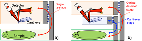
Figure 2. a) Arrangement for conventional AFMs, including most commercially available AFMs, where the optical detector and the cantilever are rigidly coupled together on a single z-translation stage (red). b) Dual-stage arrangement for the Cypher family SPMs, with a short, stiff cantilever stage (blue) and a separate optical detector stage (red).
As the ray optics diagrams in Figure 3 qualitatively demonstrate, we can reduce the sensitivity of the AFM to external vibrations by making the mechanical loop between the cantilever and sample as short and rigid as possible. In a typical AFM, the mass of the optical detection system is significantly larger than that of the cantilever. Because of this, the optical detector is more susceptible to vibration. Note that any vibrational motion of the relatively massive optical detector causes fluctuations in the tip-sample force.
When, as in Figure 3a, the optical detector and cantilever are coupled together and the cantilever is in contact with the sample, vibrational motion δz between the sample and the detector-cantilever assembly are amplified by the bending of the cantilever and result in a relatively large signal at the photodetector δVPSD. This noise is “real” in the sense that the motion of the optical detector directly affects how hard the cantilever is pressed into the surface.
Instead, as shown in Figure 3b, the cantilever-sample mechanical loop in the Cypher is small and extremely stiff. This improves the vibrational immunity of the cantilever, and the cantilever-sample force is relatively stable. At the same time, the relatively massive optical detector will still be subject to vibrational motion δz. Motion of the optical detector due to vibrational noise changes the distance between the detector and the cantilever. However, this motion only couples very weakly into the measured cantilever deflection.
The dual-stage approach used in the Cypher and drawn in Figure 2b does come at some additional cost. Rather than one translation stage for engaging and for coarse vertical control of the tip-sample distance, this approach requires two. In addition, the two translation stages need to be tightly integrated and move together. While this increases the engineering challenges, it has resulted in improved stability that has more than paid off for Cypher users.
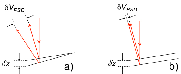
Figure 3. Simple cartoons that explain the observed improvement in noise. a) For a conventional AFM, where the cantilever and optical detector are coupled together (see Figure 2a), the vibrational motion δz is amplified by the optical lever and results in a large voltage at the position sensitive detector δVPSD. b) In the Cypher approach, the vibrational susceptibility of the cantilever is minimized with a very stiff, small mechanical loop.
The Experiment: Real-World Performance
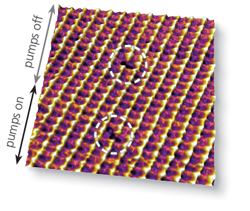
There are many ways to characterize better performance based around noise rejection, on-surface noise and so on. For this discussion, I thought a better and more fun example would be to look at the Cypher performance in a real-world, unfriendly environment: inside an operating glovebox subjected to rather noisy pumps. To get a measure of the vibration immunity of the Cypher, I also chose a demanding sample: point defect resolution in calcite. I then looked at changes in the imaging conditions as I flipped the glovebox pumps on and off. Figure 4 shows the experimental setup, with the Cypher installed inside the glovebox and the placement of the accelerometer on the table top.
Figure 4 (right). A Cypher in an unfriendly environment. An accelerometer was placed on the table and its signal measured with the auxiliary input on the ARC controller while the AFM was simultaneously being used to image a calcite surface in fluid.
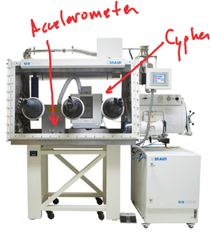 Figure 4 (right). A Cypher in an unfriendly environment. An accelerometer was placed on the table and its signal measured with the auxiliary input on the ARC controller while the AFM was simultaneously being used to image a calcite surface in fluid.
Figure 5 below shows some representative data with this setup, where the pumps were switched on halfway through a scan. During the first part of the image, the calcitesurface was measured with the pumps off. A pair of isolated point defects are visible in the image (top two red circles). Halfway through the image, I switched the pumps on while continuing the scan. The dramatic increase of the vibrational noise level on the glovebox table is clearly visible in the accelerometer signal in Figure 5b but not in the AFM image in Figure 5a, where there was no discernable change in image quality and another atomic point defect was imaged (red circle, lower left). This experiment demonstrates the remarkable vibration immunity of the Cypher platform. So we really can get atomic resolution with just a wooden table or in a conference exhibition hall—let alone in a normal laboratory.
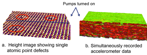
Figure 5. a) Calcite topography measured simultaneously with b) accelerometer signal in a glovebox. The pumps were turned on half way through the scan, clearly visible in the accelerometer data. Isolated defects are visible (circled in red) in the simultaneously acquired AFM topography.